Ultra-High Vacuum
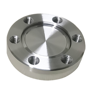
Manufactured to rigorous metallurgical thresholds under PED 2014/68/EU guidelines, our industrial slip-on components and high-tensile assemblies deliver zero-defect sealing across critical processing nodes.
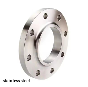
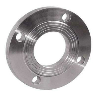
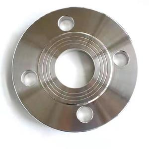
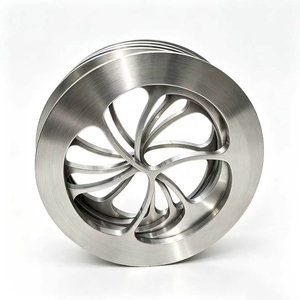
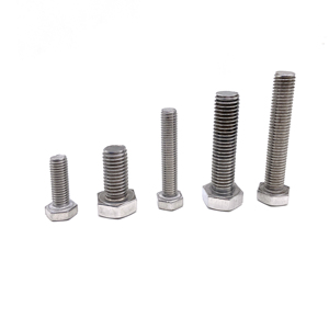
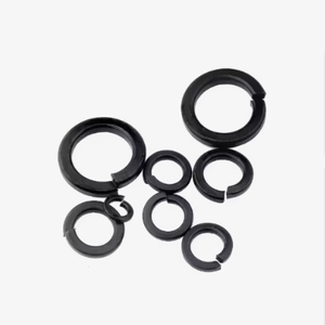
In high-pressure piping assemblies and fluid dynamics systems across LNG liquefaction, offshore refining, and chemical processing, selecting the right flange morphology dictates capital efficiency, installation cycle times, and operational risk mitigation. Slip On Flanges (SOF)—defined under ASME B16.5, ASME B16.47, and EN 1092-1 Type 12—represent one of the most widely applied mechanical joining mechanisms in industrial piping networks.
Unlike Welding Neck (WN) flanges that require full-penetration butt welding, a Slip On Flange slides over the outer diameter of the pipe. It is secured using two fillet welds: one external structural fillet applied at the rear hub, and an internal sealing fillet deposited inside the flange bore, set back from the flange mating face by a distance equal to the nominal pipe wall thickness plus 1.6 mm (1/16 inch). This dual-fillet configuration eliminates the requirement for precision bevel cutting on pipe ends, drastically reducing fit-up time and labor costs during field spool modularization.
When evaluated through Finite Element Analysis (FEA) under ANSI pressure rating classes (Class 150 through Class 1500), Slip On Flanges demonstrate unique hoop stress and bending moment curves. Because the load transfer relies on fillet welds rather than a tapered transitional neck, stress concentrations naturally localize at the hub-to-pipe junction. Under cyclical fatigue conditions, a Slip On connection typically possesses a fatigue life calculated at approximately one-third that of a corresponding weld neck connection.
However, under static pressure retaining criteria (governed by ASME Section VIII Division 1, Appendix 2), the calculated burst strength of a properly welded Slip On Flange equals or approaches that of a butt-welded joint. For low-to-medium pressure applications (PN10 through PN40, or Class 150 to Class 300), Slip On Flanges provide an exceptional strength-to-cost ratio, eliminating joint mismatch (internal misalignment or "high-low") commonly encountered when welding heavy-wall pipe to weld-neck bores.
| Flange Classification | Standard Codes | Welding Geometry | NDT Inspection Scope | Relative Field Labor Cost | Primary Application Window |
|---|---|---|---|---|---|
| Slip On Raised Face (SORF) | ASME B16.5 / EN 1092-1 Type 12 | Dual Fillet (Internal & External) | Magnetic Particle (MPI) / Dye Penetrant (DPI) | Low (No pipe beveling required) | Utility water, cooling water, Class 150/300 hydrocarbons |
| Welding Neck (WNRF) | ASME B16.5 / DIN 2633 | Single Circumferential Butt Weld | Full Volumetric Radiography (RT) / PAUT | High (Demands precision bevel fit-up) | Severe cyclic duty, cryogenic LNG, high pressure steam |
| Blind Flange (BLRF) | ASME B16.5 / EN 1092-1 Type 05 | Bolted connection (No welding) | Ultrasonic (UT) on forging plate | Minimal (Bolt torquing only) | Piping termination, isolation manifolds, inspection ports |
| Socket Weld (SWRF) | ASME B16.5 / BS 3799 | Single External Fillet (With expansion gap) | Visual (VT) + Magnetic Particle (MPI) | Moderate (Small bore DN15–DN50) | High-pressure small-diameter chemical dosing lines |
A premier Slip On Flange factory must exhibit strict control over raw billet chemistry, grain refinement, and thermal stabilization. Material selection must align with operational temperature envelopes, corrosive attack thresholds, and mechanical shock potential:
Driven by energy transition dynamics, automated modular fabrication, and digital QA traceability, international EPC contractors are upgrading their flange procurement criteria.
As green hydrogen blending penetrates natural gas distribution networks, procurement specifications now dictate tight micro-alloy limits. Flanges must maintain carbon equivalents (CE ≤ 0.41%) and restricted hardness thresholds (≤ 22 HRC) to withstand atomic hydrogen micro-cracking under cyclic compression.
Gone are the days of manual, easily misfiled paper MTCs. Progressive manufacturers integrate 2D DataMatrix laser-etching directly onto the flange rim. Scanning provides immediate cloud-hosted Mill Test Certificates (EN 10204 3.1/3.2), raw billet melt logs, and real-time ultrasonic NDT signatures.
Traditional open-die cutting often produces disjointed grain lines that reduce structural hoop fatigue limits. Modern facilities employ closed-die hydraulic presses exceeding 6,000 tons, aligning molecular grain flow along the flange hub contours while diminishing material scrap rates by 28%.
Historically, inspecting the dual-fillet weld of a Slip On flange relied on surface-only magnetic particle testing (MPI). Advanced fabrication yards now utilize customized multi-angle Phased Array Ultrasonic Testing (PAUT) rigs, allowing non-destructive volumetric inspection through the hub body.
Global supply chain volatility has driven engineering contractors away from fragmented brokerage trading. Long-term EPC agreements favor vertically integrated manufacturers operating dedicated export machining hubs with established multi-standard inventories (ASTM, EN, DIN, BS).
Demands for 30+ year maintenance-free lifespans in subsea riser connections have spurred widespread adoption of multi-layer coating systems: thermally sprayed aluminum (TSA) and Xylan/PTFE fluoropolymer overcoats over cadmium-free zinc-nickel base platings.
Combining state-of-the-art forging infrastructure with rigorous European Pressure Equipment Directive (PED) compliance to safeguard your critical flowline investments.
Fully compliant with Annex I, Paragraph 4.3 of the European Pressure Equipment Directive. Proud active member of the Fastener Manufacturers Association of India (FMAI), fulfilling stringent global audit parameters.
Ranked among India's top 3 exporters of hot-dip galvanized fastening hardware and heavy flange components. Our state-of-the-art automated spin-galvanizing facility guarantees uniform coating thickness without thread clogging.
Every single production heat undergoes complete chemical spectrometry, tensile/yield evaluation, Charpy impact toughness testing, Brinell hardness verification, and ultrasonic internal soundness scanning.
Our forged flanges and stud assemblies are actively deployed across major LNG terminals, FPSO vessels, cross-country oil pipelines, and high-speed rail civil works in the Middle East, Far East Asia, and West Africa.
Authoritative technical answers to assist piping engineers, project purchasers, and QA/QC directors in crafting bulletproof RFQs.
Slip On Flanges are primarily produced under ASME B16.5 for pipe sizes NPS ½ through NPS 24, and ASME B16.47 Series A / Series B for large-diameter pipelines from NPS 26 to NPS 60. In Europe and ISO-compliant nations, they are manufactured in accordance with EN 1092-1 Type 12 (hubbed slip-on flange for welding) across pressure designations from PN6 to PN100, as well as historical DIN equivalents such as DIN 2573, DIN 2576, and DIN 2501.
Engineering standards (such as ASME B31.3 Process Piping Code) mandate both an external hub fillet weld and an internal bore fillet weld. The external fillet provides structural resistance against mechanical line vibrations, pipeline bending moments, and axial tension loads. The internal fillet seals the crevice between the pipe OD and flange bore, preventing fluid entrapment, crevice corrosion, and erosion behind the flange face. The pipe end must stop approximately 1.6 mm to 3.0 mm short of the flange face to avoid damaging the gasket sealing surface during welding.
The Raised Face (RF) configuration concentrates bolting compression onto a defined gasket surface area (typically elevated by 1.6 mm for Class 150/300, and 6.4 mm for Class 400+), maximizing sealing pressure with semi-metallic spiral wound gaskets. Flat Face (FF) flanges have the gasket contact surface in the same plane as the bolting circle; they are required when bolting to fragile cast-iron or bronze equipment (such as cast pumps and valves) to prevent cracking the cast-iron flange due to excessive bending stress during bolt tightening.
Standard volumetric Radiography (RT) is difficult and often impractical on Slip On Flanges because the fillet weld geometry casts complex, variable-thickness shadows onto radiographic film. For projects mandating 100% volumetric weld verification, Welding Neck flanges are preferred. However, Slip On welds are routinely and reliably inspected using Magnetic Particle Inspection (MPI) or Liquid Penetrant Inspection (DPI) for surface/subsurface defects, complemented by modern Phased Array Ultrasonic Testing (PAUT).
Forged flanges exhibit continuous grain flow that contours naturally along the hub and flange ring intersection. This grain continuity delivers significantly higher impact toughness, shear resistance, and burst resistance compared to cheaper flanges flame-cut directly from rolled plate steel. Under dynamic fluid surges or sudden temperature fluctuations, plate-cut flanges risk catastrophic lamellar tearing along the plate rolling plane.
To secure an accurate engineering quote, your inquiry should clearly detail: (1) Standard & Type (e.g., ASME B16.5 Slip On), (2) Nominal Pipe Size (NPS/DN), (3) Pressure Class (e.g., 150#, 300#, PN16), (4) Material Grade (e.g., ASTM A105N, A182 F316L), (5) Facing Finish (e.g., Raised Face spiral serrated 125–250 AARH), (6) Pipe Wall Schedule (to verify bore diameter matching OD), and (7) Certification Level (EN 10204 3.1 with NACE MR0175 compliance).
Hot-dip galvanizing deposits a protective zinc layer ranging between 45 to 85+ microns. Reputable manufacturers ensure that bolt holes and critical bore dimensions are machined with calibrated allowances prior to galvanizing, or re-tapped/cleared post-galvanizing, ensuring smooth bolt insertion and proper pipe fit-up without field grinding that could compromise zinc barrier integrity.
Yes, provided the base forgings satisfy NACE MR0175/ISO 15156 requirements. This includes restricted chemical composition (sulfur ≤ 0.010%), controlled carbon equivalent, hardness testing below 22 HRC, and mandatory post-weld heat treatment (PWHT) where applicable to prevent sulfide stress cracking (SSC) in the heat-affected zone (HAZ) of the fillet welds.
Consult with our technical sales engineers to review project specifications, metallurgical requirements, and mill delivery schedules. Fully certified under PED 2014/68/EU with complete EN 10204 3.1 inspection certification.